Frequently Asked Questions
Note: Answers are for typical/standard units. If you have a custom unit or unique applications please send us an email, we are happy to help you select the best hardware for your application.
List of FAQ
- What is a piezo actuator?
- How does a piezo actuator work?
- What can I use a piezo actuator for?
- What are the advantages of piezo actuators?
- What are a piezo actuator's voltage limits?
- Can I use a power supply to operate a piezo actuator?
- What do I need to operate a piezo actuator?
- What waveform should be used to drive a piezo actuator?
- How do I confirm a third party amplifier is suitable?
- Why is the operating frequency limited to 1/2 of the unloaded resonant frequency?
- How does signal electronics noise affect a piezo actuator?
- How does piezo hysteresis affect the actuator?
- How should a piezo actuator be mounted?
- What is "blocked force"?
- Do piezoelectric stacks self-heat?
- How do I prevent damaging the piezo actuator?
- What are the preferred environmental operating conditions for piezo actuators?
What is a piezo actuator?
A piezo actuator is a device based on material that exhibits the piezoelectric effect. The piezoelectric effect is the ability of certain materials to generate a voltage in response to applied mechanical stress. The effect is reversible so when subjected to an externally applied voltage, the material can change shape by a small amount.
Piezo materials expand or contract with applied electrical charge. When assembled into a piezo stack (many parallel layers), applied voltage effects travel on the order of 0.1% to 0.2% of the piezo stack length. In piezo actuators, this travel becomes useful as actuation work (power) for a variety of applications. Piezo stack linear actuators might be considered as expanding springs, able to provide force and displacement as the control voltage drives them to expand/contract.
How does a piezo actuator work?
The active piezo stacks in DSM’s piezo flexure actuators are located in the center of a surrounding flexure-frame. DSM’s flexure-frames provide mounting options to guide travel, compressive preloads to protect the piezo ceramic, and solid-state flexures to enhance response. To mechanically amplify the small piezo travel range, DSM’s amplified flexure-frames use kinematic levers to amplify travel up to 10 mm. Since output travel is controlled directly by input voltage, piezo flexure actuators provide proportional displacement response. Solid-state flexures within DSM’s actuator frames provide quiet, lubrication-free, vacuum compatible and nonmagnetic travel possibilities.
What can I use a piezo actuator for?
Piezo-actuators are used where precision motion and/or high frequency operation is required. Piezo-actuators can produce smooth continuous motion with resolution levels at the sub-nanometer level. This property makes them useful in: precision positioning and scanning systems.
The very fast response times, wide operating bandwidth, and high specific force are beneficial for:
· fluid valve control
· optical scanning
· vibration isolation and control
· precision machining.
What are the advantages of piezo actuators?
Given the relatively small displacement that a piezo stack can develop, piezo actuators have unique design considerations. For example, piezo actuators excel in precision positioning applications where small, high-force moves are desirable. When fabricating, measuring, or testing extremely small structures or features, piezo actuators can provide very smooth and continuous motion over a range of a few microns to a few millimeters. With proper system design, piezo actuators hold the potential for high speed operation. Generally, the response time of a piezo stack is limited by the speed of sound in the material. Therefore, natural frequency of a piezo stack may be several kilohertz. Even with the added mass and lower stiffness of an amplification mechanism, the natural frequency of an amplified piezo actuator may be a few kilohertz.
Additionally, when designed and constructed properly, piezo actuators can exhibit the following strengths:
- Solid-state construction with zero backlash, stiction, or cogging
- Low or zero power position hold capability
- Very high frequency response (bandwidth)
- Very high force per unit area (force and stroke directly scale with size)
- Little or no outgassing or particle generation as flexure-based designs have little or no friction and require no lubrication
- Relatively low heat generation
- Highly scalable and reliable
What are a piezo actuator's voltage limits?
The recommended voltage limit for DSM’s standard piezoelectric stack is a signal operating between -30 V and +150 V DC. It is preferable to drive the actuator with a sine wave as input for high frequency actuation, because the extremely high-frequency components of square waves and triangle waves will decrease the expected life of the piezo stack, eventually leading to premature stack failure. When operating a piezoelectric actuator, take care not to subject the device to voltage spikes at or near maximum voltage, (which can occur when turning on an amplifier), as these spikes can also damage the piezo stack. Piezoelectric materials are very responsive, and high frequency drive signals can cause the material to experience damaging tensile stresses.
Can I use a power supply to operate a piezo actuator?
The actuator can be operated at static or near-static conditions using only a power supply and a voltmeter. The input voltage can be adjusted until the desired displacement level is achieved. Use the voltmeter to verify that the input signal is within the actuator’s rated voltage range (i.e., -30 V to +150 V). At higher humidity levels, prolonged DC voltage can lead to stack degradation.
What do I need to operate a piezo actuator?
Typical dynamic operation of a Flextensional Piezo Actuator (FPA) device involves an analog output device (e.g., function/signal generator, data acquisition card) and a piezo linear amplifier.
What waveform should be used to drive a piezo actuator?
A sinusoidal waveform should be used. DO NOT drive an actuator with a step input or square wave. If rapid response is required, DSM Piezo recommends using a half-sinusoidal transition with frequency not exceeding 50% of the actuators first natural frequency corresponding to the loaded condition. The high frequency components of a triangle or square waveform will decrease the expected life of the piezo stack, eventually leading to premature stack failure.
How do I confirm a third party amplifier is suitable?
Prior to connecting the piezo stack in the FPA actuator to the piezo linear amplifier device, DSM recommends auditing the analog signal. Use the piezo linear amplifier to drive a capacitor that is equal to the capacitance of the piezo actuator and rated for high voltage levels. Monitor the voltage applied to the capacitor from the linear amplifier with an oscilloscope to ensure that the voltage limits and waveform are appropriate for the rating of the piezo stack. Use proper electrical caution while working with all high voltage devices and connections.
Why is the operating frequency limited to 1/2 of the unloaded resonant frequency?
During dynamic operation, it is important that the actuator is not driven at or near the actuator’s loaded resonant frequency. Operation at or near the actuator’s loaded resonant frequency may cause the displacement of the mechanism to exceed the actuator’s rated displacement. If a FPA actuator is driven in a dynamic manner where it exceeds its rated stroke by more than 20%, high cycle fatigue may occur in the flexure elements of the actuator frame. In high cycle fatigue, the flexures may snap and the piezoceramic may electrically fail as a result of unbalanced loading.
How does signal electronics noise affect a piezo actuator?
The piezoelectric stack is very responsive to electrical ripple on the input signal. If the input signal has a low-amplitude, high-frequency ripple component, the actuator frame may not dynamically respond with corresponding motion, but the piezoelectric stack may respond and vibrate or chatter within the frame. For example, if a low-resolution motion card or DAC (digital to analog conversion) card is used to produce the signal to the piezoelectric device, there might be some filtering ripple on top of the input signal. If the noise is not filtered out, it may manifest itself as a high frequency noise that can be heard emanating from the actuator. Although the actuator frame cannot respond dynamically to these signals, the piezo stack has the ability to respond and follow voltage signals up to 20 kHz.
How does piezo hysteresis affect the actuator?
Actuator motion is proportional to the voltage applied to the piezo stack. The actuator motion is extremely repeatable due to the solid-state nature of the device and the sensitivity of piezo material to the applied voltage.
When a piezoelectric actuator is cycled from one voltage level to another and then back, a hysteresis behavior can be seen in the actuator’s response. The hysteresis exhibited by the actuator displacement plot is a function of the piezo material not mechanical issues. Piezo hysteresis is extremely repeatable. The plot below depicts the displacement hysteresis of a FPA actuator vs. applied voltage.
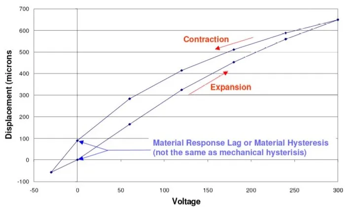
The two curves shown in the graph are representative of the hysteresis at full voltage stroke, and this is quantified as 10-15% for typical piezoelectric materials. In practical application, the presence of hysteresis dictates that the actuator’s position at a given voltage level will be slightly different depending upon whether the voltage was attained by increasing or decreasing the applied voltage. The value of the difference is a percentage of the entire voltage change. For example, if the applied voltage change corresponds to a motion change of 50 microns, there is 5 to 7.5 microns of hysteresis, etc.
Implementing a closed loop control algorithm can reduce or eliminate hysteresis. Contact DSM for the latest research and options for overcoming the effects of hysteresis.
How should a piezo actuator be mounted?
FPA actuator devices are designed to accept loading directly through the axis of motion. The loading should be applied orthogonal to the mounting surface of the actuator output block (Y-axis as shown in the figure below).
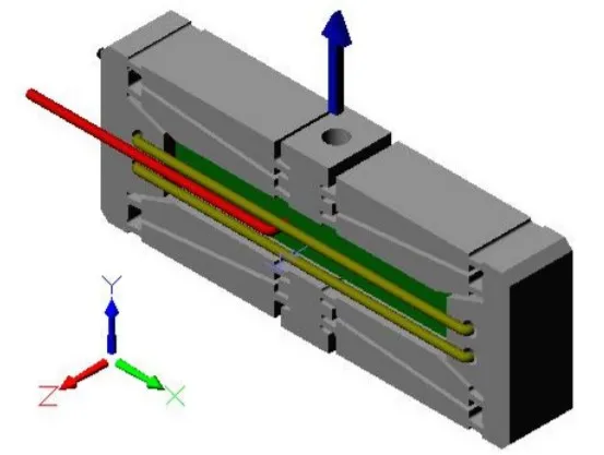
All loading must be applied uniformly and axially through the mechanism. Lateral or transverse shear loads and bending loads may cause damage to the actuator frame. This limitation applies to both static and dynamic loading and any combination of the two. Care should be applied to verify that any dynamic loading (operating at high frequency with an attached mass) does not exceed the recommended load.
Mounting Recommendations
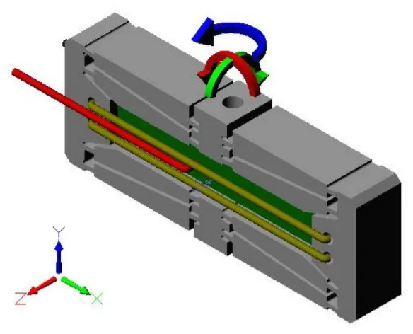
- When attaching the actuator to a mounting surface, use a clamp or wrench to support the actuator output block to prevent the Y-axis twisting moment from damaging the actuator.
- Use a spherical coupling or flexure coupling to prevent X-axis and Z-axis moments from damaging the actuator during electrical operation or actuator motion.
- Apply a linear guidance bearing to the moving output to carry any moment loads that may be present and to prevent them from damaging the actuator.
What is "blocked force"?
DSM defines a piezo actuator’s “blocked force” as being that force which is required to compress/extend a fully extended/contracted actuator back to its zero position. In most cases, DSM designs the actuator’s flexures such that the blocked force corresponds to the flexures’ maximum design stress. Even under a static load equal to an actuator’s block force, the actuator will be able to move through its full range of motion and will respond rapidly to changes in the applied voltage field. The static load simply shifts the actuator’s static position. An analogous situation is to think of the piezo actuator as a spring that has a static load placed upon it. The static load compresses the spring (piezo) to a new static position. Subsequent changes in temperature (voltage) cause the spring (piezo) to change dimensions.
Piezo actuators have an inverse, linear relationship between their force capacity (for pushing against a spring-type load) and their displacement. At zero displacement, an actuator has maximum force capacity, and at maximum displacement the force capacity has dropped to zero.
Example:
DSM’s FPA-0150E-S-0518 has a rated stiffness of 0.8 N/micron and a rated displacement of 132 microns over the 0 V to 150 V range. Therefore, the maximum recommended load (blocked force) is 106 N for this model.
Do piezoelectric stacks self-heat?
Piezoelectric materials are capacitive in nature, but these materials also have some internal, resistive losses that can lead to destructive self-heating under high dynamic operation. High levels of electrical current can flow in and out of the actuator depending upon the driving waveform and the associated rate of change of the applied voltage field. Peak current for a “straight line” voltage change is calculated as Current (Amps) = Capacitance x dV/dt (where dV/dt is the instantaneous change in voltage with respect to time). The rate of change in voltage with respect to time is directly related to operational frequency. Operation with a square wave driving waveform usually requires a very high change in voltage in a very short time span. Please check the expected operational current and heat up before using the piezoelectric actuators in applications where the duty-cycle or operational frequency may cause the external stack temperature of the piezo stacks to exceed 80 °C.
A smaller cross section piezo stack (e.g., 5x5 mm cross section) can likely be driven over a 0-150 V range at up to 300-350 Hz continuously without exceeding a steady-state stack temperature of 80 °C. A larger stack (e.g., 10x10 mm cross section) would be likely limited to approximately 150 Hz for 0-150 V continuous operation in order to maintain the steady-state surface temperature below 80 °C.
The heat-up of the actuator depends on the application duty cycle among other factors. As a result of the many factors that can affect the thermal condition of the piezoelectric stacks, please consult with DSM regarding your requirements. DSM cannot guarantee satisfactory performance under all conditions.
How do I prevent damaging the piezo actuator?
DSM’s flexure-guided piezoelectric actuators incorporate advanced materials and engineering for precision motion. The piezo actuators can easily be damaged from improper use and/or exposure to harmful environments. Improper uses include but are not limited to applications such as the following examples:
- DO NOT: introduce static compressive loads exceeding 100% of an actuator’s blocked force rating.
- DO NOT: drive the actuator in a way that creates impacts between the actuator and other rigid surfaces. Strive to avoid dropping the actuator.
- DO NOT: cycle the actuator beyond 80% of the first natural frequency corresponding to the load condition.
- DO NOT: introduce loading conditions that create bending moments in the actuator’s frame.
- DO NOT: introduce lateral or transverse loading of the actuator’s output pad or mounting point that exceeds 5% of the actuator’s blocked force rating.
- DO NOT: drive an actuator with a step input or square wave. (If rapid response is required, DSM recommends using a half-sinusoidal transition with frequency not exceeding 50% of the actuators first natural frequency corresponding to the loaded condition).
- Accidental, extreme voltage changes may damage the piezo material within the actuator. Extreme voltage changes may occur if a power plug is pulled or a piezo amplifier “overvoltages” or “undervoltages” the piezo actuator. DSM recommends using only DSM piezo amplifiers with DSM piezo actuators.
- DO NOT: introduce tensile loading into actuator frame. Prying or twisting of the actuator frame may damage the mechanism.
- DO NOT: allow the piezo within the actuator to come in contact with water. All water and alcohol liquid must be removed prior to operation. Humidity levels must be reduced to the level recommended in section 11. Note that isopropyl alcohol may have high levels of water and should not come in contact with the actuator.
What are the preferred environmental operating conditions for piezo actuators?
A standard piezoelectric actuator will be designed to operate in the following environment:
- Environmental temperature for full stroke operation at less than 200 Hz: 15 to 50 °C*
- Percent relative humidity: 0 to 50%
- Operating supply voltage: -30 to +150 V**
* NOTE: The output stroke of piezoelectric material decreases linearly from room temperature (25 °C) down to -273 °C, where displacement output is assumed to be zero. With this in mind,the motion range of a standard piezoelectric actuator will be about 20% less at -40 °C than at room temperature.
** This is the typical operating voltage for the majority of DSM’s actuator products, but some products are rated for up to 200 V.
Vacuum and Specialty Environments
DSM’s customers have used our piezoelectric actuator designs in vacuum and specialty environments (MRI, etc.) with great success. The performance of the actuator in any unique environment is the responsibility of the user.