Goniometer Stages
Traditional Goniometers
In surface science, a goniometer is a tool used to measure various properties of a surface at precise angles. Properties include static and dynamic contact angles as well as surface tension. Goniometers are very useful tools in the field of optomechanics.
Custom Goniometers
DSM has designed and built goniometers for a variety of applications. DSM has experience with gonioreflectometers, spectrometers, reflectance distribution, and general material characterization.
The engineers at DSM are capable of designing and building goniometers for single/multiple axes positioning. High position resolution can be achieved depending on the scale of the application. Goniometers can highly automate procedures.
DSM is capable of playing a role in any or all parts of the design process. Depending upon the application and customer requirements, DSM can integrate a complete motion system based on custom components and/or industry standard equipment including National Instruments motion products.
Robotic Manipulators
Many of the optical goniometers designed and built by DSM are robotic manipulators built with the intent of optical application. The Robotic Optical Scatter Instrument (ROSI) is a great example of this. The robotic manipulation technology developed by DSM and used in the ROSI is technology that is relevant to a variety of other applications. DSM does not work exclusively with optics and is open to designing a custom robotic manipulator for your project.
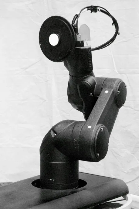
Non-Magnetic 3-Axis Goniometer
DSM developed a fully nonmagnetic 3-axis high-travel/high accuracy rotational positioning system for use inside a 3-axis Helmholtz coil. The video above shows the stage demonstrating some of its high range of motion, servoing to each position and holding in its low power state before transitioning to the next one. This goniometer is capable of 180 degrees of rotation around the X and Y axes and 360 degrees of rotation around the Z axis. Each axis is equipped with a high resolution encoder capable of determining the angle of the axis down to better than 8 millidegrees (or 140 µrad). Fully nonmagnetic piezoelectric motors are directly coupled to each axis, providing true zero backlash. Cable chains are used to route all motor control and feedback signals throughout the stage system. Two power/signal lines run through the cable system to connect power and communication signals to the "device under test".
The goniometer stage positioned the "device under test" at any point inside its range of motion, where it could be operated in a predetermined orientation inside a specified magnetic field. The controller was located outside the system. The self-locking nature of the piezoelectric motors meant that, once in position, the stage could effectively be powered off without moving. When not moving, the stage only required power to the encoders to maintain current stage positioning. The stage was constructed with absolutely no magnetic materials (including no stainless steel fasteners) and generated virtually no magnetic fields due to its ultra-low standby power draw.
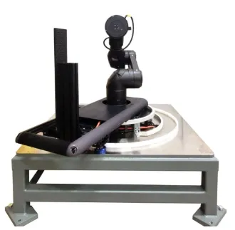
Robotic Optical Scatter Instrument
The Robotic Optical Scatter Instrument (ROSI) was designed and constructed by DSM. The surface goniometer allows researchers at the the National Institute of Standards and Technology (NIST) to automate the data collection process needed to generate bidirectional reflectance distribution functions. The system’s design specification and acceptance testing procedure were developed to ensure that samples ranging from a less than an inch in diameter to over 12x12” square could be positioned and oriented with the accuracy required by an agency whose very name is synonymous with accuracy. The system uses a commercial off-the-shelf (COTS) precision 6DoF (6 degrees of freedom) robot and a custom sample holder with an integrated rotation stage to precisely position and orient optical samples with respect to an incident laser and detector. This system was a robotic manipulator designed specifically for an optics application.
Click here to see the NIST Paper describing the system.
At the time of construction, ROSI represented the first robotic goniometer in the United States and one of only a handful of such systems in the world. ROSI was officially presented to the optics community at the Society of Photo-Optical Engineers (SPIE) Optical Engineering + Applications conference in August of 2013.
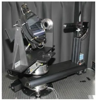
Goniometric Optical Scatter Instrument
DSM delivered a custom optical goniometer to the US National Institute of Standards and Technology. This 6DoF goniometric positioning system was developed for optical characterization of materials. It was designed for high accuracy, with encoder position feedback on all axes. Typical minimum resolutions for the linear and rotary axes were 0.5 um and 0.001 degrees, respectively. The Goniometric Optical Scatter Instrument (GOSI) can use ultraviolet and visible laser light sources. It can be used for studying low-scatter surfaces such as silicon wafers and optically smooth mirrors and can accommodate sample sizes up to 300 mm.
Click here to see the description of the GOSI on NIST’s web site.
Large Linear Excursion Goniometry
DSM was faced with the challenge of designing and building a high-precision surface goniometer with closed-loop control of six independent degrees of freedom, including over 100ft of linear displacement, for use at the National Institute of Standards and Technology’s National Calibration Facility for Retroreflective Traffic Control Materials.
DSM designed and built an automated goniometer capable of supporting samples weighing up to 10kg and measuring up to 125 cm in length. The system is capable of translating samples ± 30.5cm along the vertical axis while maintaining the samples position along orthogonal axis to within 0.005cm. DSM was able to accomplish this feat by using precision stages incorporated into a precision assembly, all mounted on 30m of precision railing.
The safety of after-dark driving depends partly on the retroreflective property of road signs, pavement markings, and other traffic control devices. However, measurements of this property, which is the materials’ ability to bounce light back from a vehicle’s headlights, have varied by as much as 20 to 40 percent between available instruments and from laboratory to laboratory. These variations and the lack of national calibration standards for retroreflectivity can lead to difficulties between signage manufactures and buyers representing state departments of transportation.
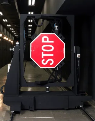
In order to resolve these variations and to establish industry standards, the National Institute of Standards and Technology (NIST) has established the Center for High-Accuracy Retroreflection Measurements. The heart of the new center is a dedicated reference instrument – a high-precision, six-axis goniometer designed by Dynamic Structures and Materials, LLC (“DSM”) and installed at NIST’s Gaithersburg, MD facility. The goniometer provides closed loop control of six independent degrees of freedom and travels 30m on a precision rail assembly. The system’s robust design is large enough to accommodate actual road signs such as the octagonal STOP sign used in the U.S. (approximately 1 m diameter).
A 50m black tunnel houses the goniometer to eliminate stray illumination that could interfere with researchers’ measurements. During experimentation, light is projected from a source (representing a headlight) onto a test object such as a road sign or pavement marking. The light is retroreflected to a photometer, which measures the amount of returning light (simulating what a vehicle’s driver might see). Measurements in the facility are traceable to the candela, a SI unit maintained by NIST.
The specifications for high angular resolution and accuracy in the goniometer’s operation resulted from the desire to use the equipment as a research instrument as well as a calibration device. Vertical deviation of the goniometer system’s center over the 30m rail length is within ±0.75mm, and horizontal deviation of the center is within ±1.0mm. Final system specifications are tabulated below:
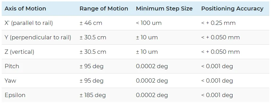
As part of the system’s post-installation characterization, NIST determined that for any one axis move, the system’s sphere of confusion is an ellipsoid of dimension 0.35 mm in the vertical direction and 0.12 mm in the horizontal direction.
Researchers at a remote PC control the motion of the system’s axes through custom software written under National Instruments’ LabWindows. MXI-3 technology, a PCI master/slave system, is used to couple the remote PC via a fiber optic data link running the length of the hallway to a National Instruments PXI-1002 chassis incorporated into the goniometer’s structure. The PXI chassis also houses two NI PXI-7334 stepper motor motion cards and a NI PXI-8421/2 card to provide an interface for RS-485 communication with the system’s 30m linear encoder.
DSM also incorporated an enclosure in the system’s structure to protect the stepper motor drives and two NI UMI-7764 Universal Motion Interfaces. The UMI boxes provide connections for step and direction signals from the motion controllers to the stepper motor drives as well as connections for the majority of the position encoders. E-stop switches installed on the goniometer frame in easy reach of any bystander are routed to relays that disable power to the system’s motors.
The accuracy of the goniometer’s motion control system over such large motion ranges is made possible through the use of high-end motion components and sensors. Five-phase Vexta Nanostep® CFKII 569 stepping motors were chosen to produce precision motion for the three rotational axis of the goniometer, while two-phase Vexta CSK 268MAT stepping motors drive the linear axes of motion. When set at the smallest step angle, the five-phase Vexta stepper motors have 125,000 steps per revolution. DSM successfully coupled the stepper motors to high accuracy harmonic drives with a 160:1 gear reduction that yielded a potential resolution of greater than 20 million steps per revolution. Using rotary encoders to provide position feedback, actual “closed-loop” minimum step size for the three rotational axes was less than 0.0002 degrees or 1.8 million steps per revolution.
DSM selected HD Systems harmonic drive gear reducers to couple with the stepping motors. The harmonic drives provide a 160:1 single stage gear reduction in a very small package. The HD systems CSF-2UH gearheads have virtually zero backlash and come with built in roller bearings to support the output shaft. The HD harmonic drives provided dramatic increases in stepper motor holding torque to control the rotation of the large goniometer support frame with authority.
Each axis of the goniometer is monitored by an encoder and limit switches. The limit switches were incorporated into the frame to protect each axis against overtravel by disabling signals to the respective axis’ motor. The encoders selected for the three rotary axes are from the Mercury 2000 family of high precision encoders from MicroE Systems, Inc. The optical encoders use glass-scales with interpolator electronics that enable up to 4.19 million counts per revolution. MicroE Systems precisely mounted the glass scales to DSM’s custom-designed encoder hubs. The encoders’ small read heads were easily incorporated into the goniometer’s structural design, and their robust tolerance to misalignment made adjustments during installation fast and simple.
With the aid of the new goniometer system’s capabilities, NIST researchers hope to achieve agreement among retroreflectivity instruments and to make federally-mandated standards more precise.